Does Mo₂C Change the Properties of Ti(C,N)-Ni-Co Cermet Structure? – UKO Blog
In this paper, Ti(C,N)-Ni-Co cermets with different contents of Mo₂C were prepared, and the influence of Mo₂C on microstructure, mechanical properties and cutting performance of 304 stainless steel were studied. The microstructure and flank wear were observed through scanning electron microscope. Based on Archimedes drainage method, Rockwell hardness tester, Vikers hardness tester and three-point bending method, the relative density, hardness, fracture toughness and transverse rupture strength were tested. The results show that with the increase of the addition of Mo₂C, the grain size of the cermet decreases, and small grain agglomeration appears at 18% (mass fraction, the same as below) addition. Hardness and relative density increase with the increase of Mo₂C. Fracture toughness and transverse rupture increase firstly and then decrease, reaching the maximum at 12% addition. The flank wear of the cutting tool is the lowest under the cutting speed of 100 m/min and 80 m/min, when the addition of Mo₂C is 12%.
304 stainless steel is widely used in aviation, chemical industry and other fields due to its good mechanical strength and corrosion resistance. However, its good plasticity makes it easy to pick up the knife during the processing, which makes the processing temperature high and affects the processing accuracy, so it has higher requirements for the cutting knife. China’s domestic 304 stainless steel cutting tools are also mainly cemented carbide, but cemented carbide tools are difficult to meet the needs of today’s high-precision high-speed cutting.
Ti(C,N)-Ni-Co cermet is obtained on the basis of cemented carbide by changing to Ti(C,N) as the hard phase. It not only has the high hardness and wear resistance of ceramic materials and Good chemical stability, also has the strength and toughness of metal materials. And because of its good thermal conductivity, it can better reduce the occurrence of thermal cracks, making it more and more widely used in cutting tools. The service life of Ti(C,N)-Ni-Co cermet tools is traditional hard 5~10 times of carbide cutting tools.
However, in the field of machining tools, one of the main reasons restricting the development of Ti(C,N)-Ni-Co cermet tools is the low toughness of the tools, and the tools are easily damaged during the cutting process. To this end, this article improves the overall performance of Ti(C,N)-Ni-Co cermet by adding Mo₂C, and studies its cutting performance on 304 stainless steel.
1 Experimental Process
1.1 Raw Materials
In this experiment, Ti(C,N), Mo₂C, TaC, WC, Ni, Co powders were used. The characteristics of the powder are shown in Table 1. Four groups of cermets with different Mo₂C contents were prepared by powder metallurgy. All unspecified are quality scores) see Table 2
| Raw powder | Fsss /μm | w(CTotal) /% | w(CFree) /% | w(O) /% |
|---|---|---|---|---|
| Ti(C0.7N0.3) | 1.85 | 13.52 | 0.08 | 0.3 |
| Mo₂C | 1.55 | 6.03 | 0.2 | 0.52 |
| Ni | 2.6 | 0.1 | 0.1 | 0.1 |
| Co | 1.5 | 0.03 | 0.5 | 0.35 |
| TaC | 0.98 | 6.23 | / | 0.12 |
| WC | 1.01 | 5.89 | 0.14 | 0.3 |
| Specimen | w(Ti(C,N)) /% | w(Mo₂C) /% | w(Co) /% | w(Ni) /% | w(WC) /% | w(TaC) /% |
|---|---|---|---|---|---|---|
| C1 | 74 | 0 | 7.5 | 7.5 | 3 | 8 |
| C2 | 68 | 6 | 7.5 | 7.5 | 3 | 8 |
| C3 | 62 | 12 | 7.5 | 7.5 | 3 | 8 |
| C4 | 56 | 18 | 7.5 | 7.5 | 3 | 8 |
1.2 Preparation Process
Weighing adopts Satorius BS224S electronic balance, and then mixes ball milling. Grinding ball adopts YG6 cemented carbide ball with Φ6 mm, and the ball to material ratio is 10:1. The mixture uses gasoline as the grinding medium at a speed of 56 r/min and grinds for 72 h. After grinding, the slurry is dried and sieved, and then mixed with an SD rubber solution as a molding agent with a mixing ratio of 220 ml/kg. The dried mixture is pressed into 20 mm×6.5 mm×5.25 mm strength bars. The green compact is sintered in a vacuum furnace ZYL-ZA150 for 1 hour at a temperature of 1445 ℃.
1.3 Cutting Experiment
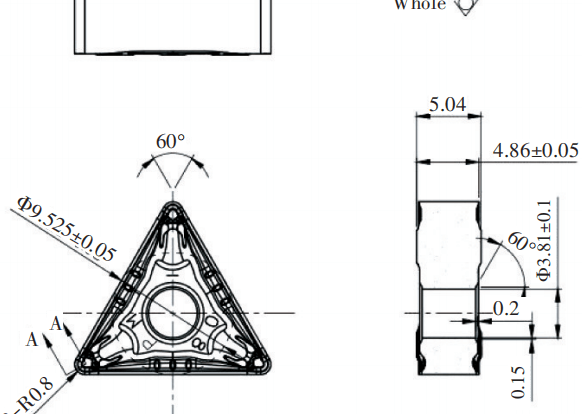
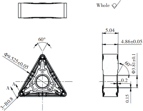
For the cutting test, commercial-grade TNMF160408 blades were used. The blade parameters are shown in Figure 1. The blades were clamped with MTJNR2020K16 shank. See Table 3 for cutting parameters. Cermet tools are mainly used for semi-finishing and finishing. Due to the high cutting speed, they are prone to chipping during the cutting process. In order to ensure the integrity of the cutting edge of each group of cutting tools during the cutting experiment, the flank face wear was specially controlled in the stable wear stage, so the experiment set a continuous cutting time of 10 minutes, and the flank face wear was measured every 2 minutes. According to the standard ISO3685, the flank wears Vb exceeds 0.3 mm is considered as destruction.
| Parameters | 1 | 2 |
|---|---|---|
| Cutting speed, v/(m/min) | 80 | 100 |
| Feed rate, f/(mm/r) | 0.1 | 0.1 |
| Depth of cut, ap/mm | 0.5 | 0.5 |
1.4 Detection
The Hitachi HITACH-S-4800 scanning electron microscope was used to observe the matrix structure of the cermet in the backscattering mode. The density was measured by the Archimedes drainage method according to the national standard GB/T3850-1983. The hardness of the cermet was adopted by Shandong Laizhou Huayin Testing Machine Factory. The HVS-50 Vickers hardness tester is used for testing. The fracture toughness is measured by the Huayin HR-150A Rockwell hardness tester by the indentation method, and the transverse fracture strength is measured by the WE-100B universal material testing machine. The cutting experiment was carried out with the CY-K360s machine tool manufactured by Yunnan Machine Tool Plant. The wear of the tool flank was measured with China Wanwei VMS-3020 image measuring instrument.
2 Results and Analysis
2.1 Effect of Mo₂C Content on Microstructure and Mechanical Properties of Ti(C,N)-Ni-Co Cermet
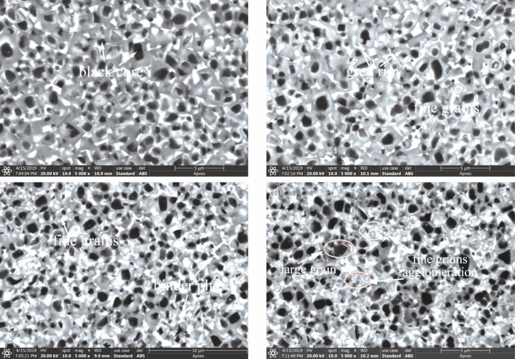
It can be seen from Figure 2 that the overall distribution of the tissue is uniform, and the core-ring structure is clear. In the backscattering mode, with the increase of Mo₂C content, the grain size is refined, and the brightness of the ring phase and the bonding phase is increased. d) At (18%Mo₂C), the phenomenon of small grains agglomerating and bunching occurs. This is due to the fact that with the increase of Mo₂C content, during the liquid phase sintering, the components dissolve and precipitate out, forming (Ti, Mo, X) (C, N) solid solution, and wrapped in Ti (C, N) On the grains, the agglomeration and growth of the grains are hindered, thereby refining the grains. At the same time, in the backscattering mode, the higher the atomic number, the higher the contrast, and the brighter the color of the ring phase and the bonding phase.
It can be seen from Table 4 that as the content of Mo₂C increases, the hardness of Ti(C,N)-Ni-Co cermet increases, this is because the addition of Mo₂C can improve the hard Ti(C,N) hard bonding phase The wettability makes the tissue more compact. At the same time, according to the Hall-Petch formula, the hardness is inversely proportional to the grain size, so the hardness value increases, and the transverse fracture strength and fracture toughness increase first and then decrease, reaching the maximum when the Mo₂C content is 12%. This is because the pores in the tissue will cause stress concentration as a source of crack growth and will accelerate crack growth. As the addition of Mo₂C increases, the structure becomes denser, so the transverse fracture strength increases. However, excessive Mo₂C will make the ring phase too thick. During the dissolution-precipitation process, the larger particles will dissolve the smaller particles and grow up excessively, and there will be small crystal grains that are not completely dissolved and then get together and become a region that is convenient for crack propagation. Shows poor resistance to crack growth. Therefore, the fracture toughness shows a phenomenon of increasing first and then decreasing.
| Samples | Hardness (HRA) | Transverse rapture strength /MPa | Fracture toughness /(MPa·m½) | Relative density /% |
|---|---|---|---|---|
| C1 | 91.66 | 1441.25 | 6.37 | 97.02 |
| C2 | 92.35 | 1743.9 | 7.58 | 97.79 |
| C3 | 93.21 | 1949.8 | 8.77 | 99.02 |
| C4 | 94.59 | 1822.5 | 7.95 | 99.68 |
2.2 the Effect of Ti(C,N)-Ni-Co Cermet Tools With Different Mo₂C Content on the Cutting Behavior of 304 Stainless Steel
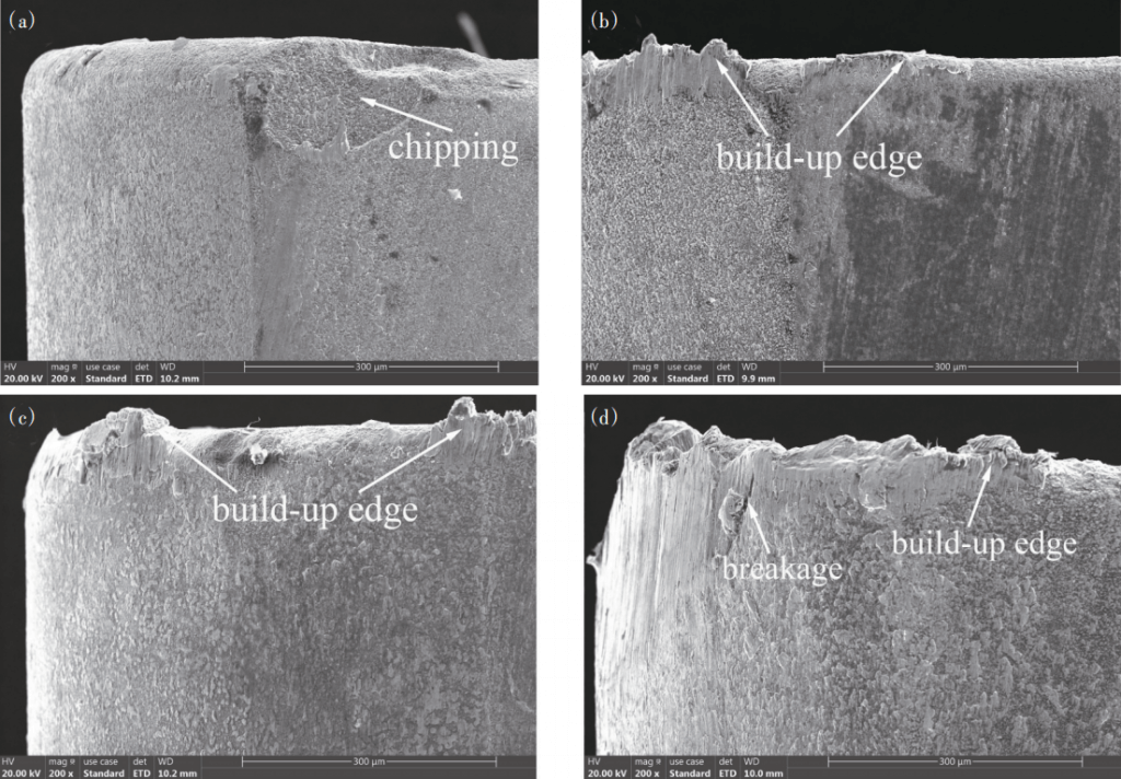
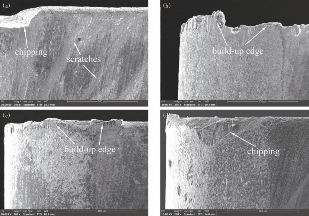
Figure 3 shows the flank wear after the continuous cutting of Ti(C,N)-Ni-Co cermet tools with different Mo₂C contents under different cutting parameters. Figures 4 and 5 show the morphology of the flank wear after continuous cutting for 10 minutes at 80 m/min and 100 m/min, respectively. Figure 5(a) shows the morphology of the chipped edge of the C1 tool after cutting for 6 minutes. Because the experiment deliberately controlled the tool wear in the stable wear stage, the standard “initial-stable-violent wear” tool wear curve did not appear in the figure.
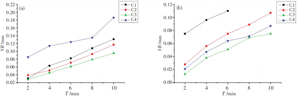
When the cutting speed is 80m/min, the flank wear of the tool decreases first and then increases with the increase of Mo₂C content. This is because the wear of the cermet tool mainly starts from the fracture of the material and the propagation of cracks. The addition of Mo₂C The blade has higher hardness, strength and toughness, so the wear of the flank face tends to decrease at the same cutting time. However, when the Mo₂C content is 18%, because the hard phase is too fine and aggregated, the cutting The probability of cracks in the process is greater, and the ability to resist crack propagation is lower, so the amount of wear increases.
Due to the low hardness and strength of the C1 tool, there is a small chipping at the edge of the cutting edge after a long period of cutting. C2~C4 tools have built-up edges at the tip and flank surface, which is due to the high hardness and toughness of 304 stainless steel It is difficult to break the chip during the cutting process, and as the cutting progresses, the temperature increases, which exacerbates the occurrence of the knife. The C3 tool has better overall mechanical properties and can better maintain the integrity of the cutting edge during the cutting process, so the chips are not easy to accumulate at the cutting edge, so the accumulation of chips is the least, and the amount of wear is also the lowest. Due to the agglomeration of fine grains, the C4 tool is the first to break down to form small grooves during the cutting process, resulting in an increase in the friction coefficient during the subsequent cutting process and a further increase in temperature, which accelerates the softening and accumulation of chips, which in turn causes Chips accumulate most at the blade.
Similarly, when the cutting speed is 100m/min, the tool flank wear decreases first and then increases with the increase of the Mo₂C content, and the wear is the lowest when the amount of Mo₂C added is 12% (C3). After cutting at the cutting speed of 80m/min and 100m/min for the same time, the flank wear of C2, C3 and C4 tools is lower at the cutting speed of 100m/min. This is because when cutting 304 stainless steel, the cutting force decreases as the cutting speed increases. The higher the cutting speed, the higher the temperature, which makes the 304 stainless steel soften during the cutting process, which reduces the friction coefficient and reduces the cutting force. However, the wear of the flank face of the C1 tool increases with the increase of the cutting speed. This is because the transverse fracture strength and fracture toughness of the C1 tool are the lowest. When the speed increases, the number of times the tool is impacted by the material per unit time More, the probability of crack generation is greater, so the amount of wear does not fall but rises, and even chipping occurred at 6 minutes of cutting.
3 Conclusion
- Through the observation of the microstructure, it is found that with the increase of the amount of Mo₂C, the cermet hard phase grain refinement is obvious. The microstructure is the most uniform when the amount of addition is 12%, and appears when the amount of addition is 18%. The phenomenon of agglomeration and bunching of large and small grains.
- Through the observation of the microstructure, it is found that with the increase of the amount of Mo₂C, the cermet hard phase grain refinement is obvious. The microstructure is the most uniform when the amount of addition is 12%, and appears when the amount of addition is 18%. The phenomenon of agglomeration and bunching of large and small grains.
- The cutting test shows that at a cutting speed of 100 m/min, the wear of the flank of the tool is lower than that at 80 m/min. The flank wear decreases first and then increases as the Mo₂C content of the tool increases. For tools with a Mo₂C addition of 12%, the flank wear is the lowest.