Prince Fastener:Quantitative evaluation method of fastener anti-loosening performance Screws and Fasteners Manufacturer
Prince Fastener:Quantitative evaluation method of fastener anti-loosening performance
The equipment was improved based on the existing transverse vibration test method, and the critical transverse force leading to rotational loosening was proposed as the quantitative index for evaluating the loosening performance. The specific test method and data acquisition method were given. The proposed method’s loosening performance of spring washers, wedge nuts and eccentric double nuts was quantitatively tested and compared. (3) The loosening prevention performance of the eccentric double nut is improved by up to 125% compared with the normal threaded connection under the same preload.
Introduction
Threaded joints are generally simple, easy to assemble and disassemble, reliable, interchangeable, and inexpensive, and are widely used in various mechanical products and engineering structures. Many engineering experiences have shown that threaded joints are prone to loosening and failure under vibration conditions. The loosening of threaded connections seriously impacts the reliability and life of mechanical products, and quality problems and accidents caused by the loosening of threaded connections are common in engineering. Fasteners with anti-loosening properties, such as lock washers and nuts, are often used to prevent the loosening of threaded joints. However, to what extent do the various locking fasteners improve the loosening performance of threaded joints? There is no precise answer to this fundamental question. This has caused controversy and posed many problems in the design, manufacture, selection and use of fasteners.
Engineers usually test the loosening performance of fasteners based on two vibration test methods specified in the national standard GB/T 10431-2008 [1] or the national military standard JGB 715.3A-2002 [2]. Based on the first test method, the loosening performance of a fastener is usually evaluated based on the amount of preload remaining in a given vibration cycle (usually 1500 cycles); based on the second test method, the loosening performance of a fastener can be evaluated based on the duration of the fastener before it breaks loose. Although these two methods can evaluate the loosening performance of fasteners supplier to a certain extent, they can only be used to qualitatively compare the relative strength of different fasteners’ loosening performance or to judge whether a fastener can pass the test of specific vibration conditions, but cannot quantitatively evaluate the loosening performance of fasteners due to the limitations of test equipment and data processing methods.
The first difficulty of quantitative evaluation of fastener loosening performance is establishing the quantitative evaluation index (or index system) of loosening performance, i.e., to clarify what scale should be used to evaluate the loosening performance of fasteners. This paper adopts the basic idea of the transverse vibration test method recommended by the national standard GB/T 10431-2008 [1] but improves and perfects the test equipment and proposes quantitative evaluation indexes and data acquisition methods for the loosening performance of threaded joints by analyzing the decay law and mechanism of the preload force. Based on the proposed method, the loosening performance of spring washers, wedge nuts (typically Spiralock® nuts) and eccentric double nuts (typically HARD-LOCK® nuts) was quantitatively tested and compared. The wedge nut and the eccentric double nut are generally considered to have excellent loosening performance and have been used more and more in China in recent years. It should be noted that the fasteners mentioned in this paper only refer to fasteners used for threaded connections, including various nuts, bolts and washers, and do not include other types of fasteners such as rivets and pins.

01
Existing transverse vibration test equipment limitations and improvements
The transverse vibration test method used in the existing national standard GB/T 10431-2008 [1] was first published in 1969 by the German engineer JUNKER [3], who systematically verified that transverse vibration loads can cause loosening of threaded joints and is therefore often referred to as the Junker test method. The industry has widely accepted the Junker test method and has formed a standard method for fastener loosening tests based on the Junker tests method.
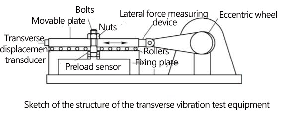
Figure 2 shows the structure of a transverse vibration test equipment that meets the requirements of the national standard GB/T 10431-2008 [1]. The specific structure of the test equipment produced by different manufacturers may not be the same as in Figure 2, but the principles are the same. The test equipment is shown in Fig. 2 mainly consists of an eccentric wheel, a movable plate, a fixed plate, a preload transducer, a transverse force measurement device and a transverse displacement transducer. The bolts and nuts (washers can also be added) are first tightened to the set preload force during the test. Then the eccentric wheel generates reciprocating transverse motion under the action of the motor. The maximum transverse displacement (i.e., amplitude) is controlled by the eccentric amount of the eccentric wheel. The transverse force can be recorded in real-time by the transverse force measuring device. Under the transverse vibration load, the threaded connection will be loosened gradually, and the preload force will be reduced gradually. The preload force sensor can record the change of preload force during the vibration process in real-time. In addition, the actual amplitude of the movable plate during the test can be recorded by the transverse displacement sensor in real-time.
The transverse vibration test equipment shown in Figure 2 can only control the amplitude in an open loop. Specifically, the amplitude is controlled by the eccentricity on the eccentric wheel, which is often unstable because structures such as connecting rods and transverse force measurement devices compress or elongate under transverse forces, resulting in a large discrepancy between the actual amplitude and the set eccentricity of the threaded connection. Figure 3 shows the variation of the actual amplitude with the vibration period of an open-loop controlled transverse vibration test equipment. The test specimen is M10, the initial preload is 25kN, the vibration frequency is 12.5Hz, and the set eccentricity is 1mm.
The actual amplitude of the threaded connection is closely related to the amount of transverse force it is subjected to and is a key factor in loosening the threaded connection. The loosening of threaded joints results from a combination of external and internal factors, with the amplitude being the main external factor and the fastener’s own ability to prevent loosening being the internal factor. Since the external factors are uncertain under open-loop control conditions, it is impossible to distinguish the quantitative effects of the internal factors from the test results (i.e., the decay of the preload force). To solve this problem, this paper proposes the concept of closed-loop control of transverse force in the transverse vibration test. It improves the existing transverse vibration test equipment with the function of closed-loop control of transverse force. The maximum range of transverse force measuring device in the improved test equipment is 50 kN, the maximum range of preload measuring device is 100 kN, and the maximum range of transverse displacement measuring device is 10 mm. The errors of the above three quantities do not exceed 0.5% of the calibration value.
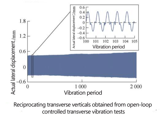
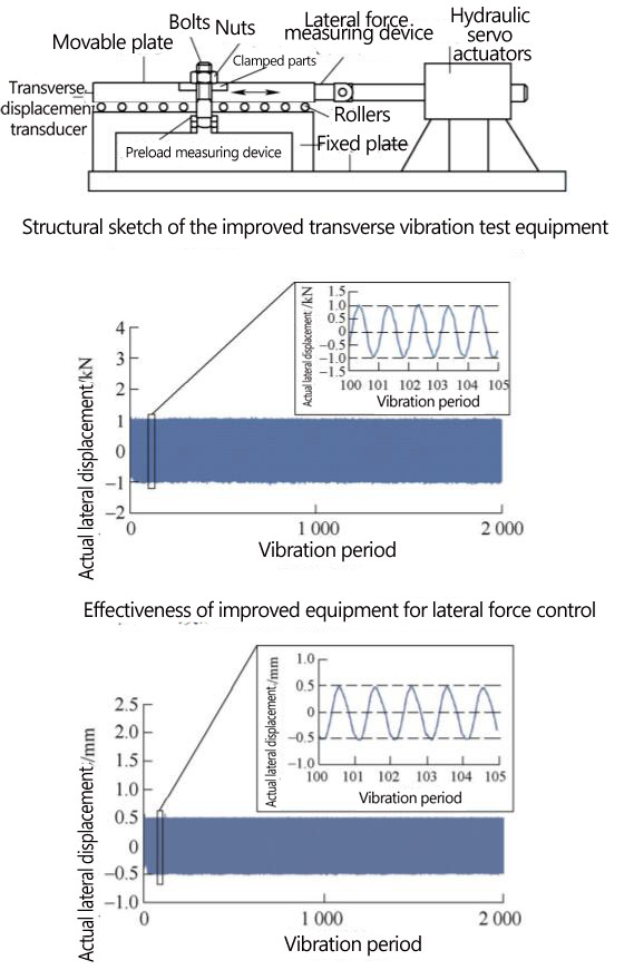
Figure 4 shows a sketch of the structure of the improved transverse vibration test equipment, which is based on the measured data of transverse force to adjust the control parameters of the hydraulic servo actuator to realize the closed-loop control of transverse force; in addition, the equipment can also be based on the measured data of transverse displacement to realize the closed-loop control of transverse displacement. Figure 5 shows the variation of the actual transverse force with the vibration cycle of the improved transverse vibration test equipment in a certain test, the test specimen size M10, the initial preload force is 18 kN, the vibration frequency is 5 Hz, and the set transverse force is 1 kN. Figure 6 shows the variation of the actual transverse displacement with the vibration period of the improved transverse vibration test equipment in one test, the test specimen size M10, the initial preload force is 25 kN, the vibration frequency is 5 Hz, the set amplitude is 0.5 mm, and the measured results show that the equipment also has high control accuracy on the transverse displacement. The subsequent tests in this paper are based on the improved transverse vibration test equipment.
02
Quantitative evaluation of the loosening performance of threaded joints and data acquisition method
To quantitatively evaluate the loosening performance of fasteners, it is necessary to establish scientific indicators for quantitative evaluation of the loosening performance of threaded joints. Since the decay of the preload force is the result of a combination of factors, it is necessary to distinguish the influence of different factors on the decay of the preload force to evaluate the loosening performance accurately. It has been demonstrated [6-11] that the typical decay of preload in a threaded joint under transverse vibration test conditions can be divided into three stages, as shown in Figure 7. In the first stage, the preload decays rapidly and non-linearly. The main cause of this decay is the plastic deformation of the material, stress redistribution, rotational loosening and microwear. In the second stage, the preload decreases approximately linearly, with rotational loosening between the inner and outer threads being the main cause of the decay, while other factors have relatively little effect. In the third stage, fatigue cracks gradually appear in the threaded structure, leading to a faster decay of the preload and even sudden fracture. Figure 8 shows a measured preload decay curve based on the improved test equipment, using an M10 sample with an initial preload of 25 kN, an amplitude of 0.5 mm and a frequency of 12.5 Hz.
To obtain a quantitative evaluation of the loosening performance of the fasteners from the preload decay data shown in Figure 7, it is necessary to clarify the exact meaning of “loosening” and “loosening performance”. Rotational loosening refers to the rigid rotation between the internal and external threads that causes the preload decay, which corresponds to the second stage in Figure 7; non-rotational loosening refers to the decay of the preload caused by factors other than rotational loosening. We define “loosening resistance” as the ability to prevent the rotational loosening of the threaded connection. It is closely related to the data from the second stage of the preload decay process.
This definition of loosening performance is based on the fact that loosening fasteners are primarily designed to prevent rotational loosening. It is difficult to inhibit non-rotational loosening that leads to preload decay.
Based on the above definition, ideally, when the slope of the second stage of the curve shown in Figure 7 is zero, no rotational loosening of the threaded joint occurs; when the slope of the second stage is less than zero, rotational loosening occurs, and the larger the absolute value of the slope, the more severe the rotational loosening.
In addition, it has been proved in a study [7] that there is a critical value of transverse force. When the transverse force on the threaded connection is less than this critical value, no rotational loosening of the threaded connection occurs. When the transverse force on the threaded connection is greater than this critical value, rotational loosening of the threaded connection will occur. Therefore, the critical value of transverse force (or critical transverse force) can be used as a quantitative evaluation index for the loosening performance of fasteners (or threaded connections). It should be noted that this index is based on the transverse vibration test conditions described in this paper and does not apply to other forms of external loads.
Figure 9 shows the decay curve of the preload force at different transverse forces for a sample of M10 with an initial preload force of 18 kN and a frequency of 5 Hz. When the transverse force was 1.3 kN, the absolute value of the slope increased significantly, and the threaded joint showed significant rotational loosening.

The test results shown in Figure 9 indicate that the critical transverse force does exist. However, there are still two problems to be solved to determine the value of the critical transverse force accurately: (1) since the preload force changes gradually, it is impossible to determine the turning point between the different stages accurately. (2) Ideally, when the slope of the second stage is zero, there is no rotational loosening of the threaded connection. In reality, due to wear, temperature changes, measurement errors, data processing errors, etc., the measured slope of the second stage is not exactly zero. These two problems are described in the following.
To obtain the absolute value of the slope of the second stage quantitatively, a method is proposed in this paper: as shown in Fig. 10, firstly, the measured preload force curve is divided into m segments for every specific cycle n; then, based on the least squares method, a linear fit is performed for any segment I curve to obtain the absolute value of the slope of the segment I curve ai, as shown in Eq. 1, where j represents the jth vibration cycle, I j is the average value of the vibration cycles in a segment I curve. The equation is shown in Equation 1, where j represents the jth vibration period, I j is the average value of the vibration period in the i-segment curve, yj is the remaining preload force at the jth vibration period, and I y is the average value of the remaining preload force in the i-segment curve.
Figure 11 shows a series of absolute values of slope based on the preload force variation data of 1.1 kN in Fig. 9, with a period interval of 300. Among all the absolute values of the slope, the smallest value can be selected as the absolute value of the second stage slope of the preload force decay curve in N/period, which corresponds to point A in Fig. 11. To compare the results under different preload forces, the absolute value of the slope can be normalized by dividing the absolute value of the slope by the initial preload force of the group and multiplying it by 100% to obtain the normalized slope in %/cycle, which can be expressed by Equation 2, where k is the final normalized slope and F0 is the initial preload force.
Once the normalized slope is obtained, it is necessary to find the critical point where the rotational slack occurs according to the normalized slope to determine the critical transverse force. In this case, a reasonable slope threshold is selected, and rotational slack is considered to occur when the actual normalized slope is greater than this threshold.
To select a reasonable threshold value, some experiments must be conducted. Based on many experimental studies, this paper summarizes the typical relationship curve between lateral force and normalized slope, as shown in Figure 12. In phase A, the normalized slope value is small and increases slowly as the transverse force increases. The normalized slope value increases rapidly with increasing transverse force in phase B, implying a significant rotational loosening of the thread connection. The normalized slope value at the turn of the curve from phase A to phase B corresponds to the threshold at which rotational loosening begins, as shown by the dashed line in Figure 12.
03
Experimental design
Based on the test above method, quantitative evaluation index and data acquisition method, a set of tests was designed to quantitatively test the loosening performance of spring washers, wedge nuts and eccentric double nuts. The information of the test specimens is shown in Table 1, among which the common bolts conform to GB/T 5783-2016 [12], the common nuts conform to GB/T 6170-2015 [13], and all the test specimens were ultrasonically cleaned before the test.
The test was divided into four groups according to the type of fasteners used, as shown in Table 2, in which Group 1 was the control group, and the rest of the groups were compared with Group 1 to analyze the loosening prevention performance quantitatively. The eccentric double nut tightening process in this study is based on the study of Li Tianlei et al. Each test group was divided into six groups according to the initial preload force, and each group contained several different transverse force conditions, as shown in Fig. 3, with a sampling interval of 0.1 kN for each test piece.
When the normalized slope of one or more tests under a certain test condition is greater than the slope threshold, it is considered that rotational loosening has occurred under that test condition. When the normalized slope of three repetitive tests is less than the slope threshold, it is considered that rotational loosening has not occurred under that test condition. Only when the normalized slope of the three repetitive tests is less than the slope threshold is it considered that no rotational slack has occurred under the test condition.
04
Test results
4.1 Determination of the slope threshold
In the test, it was found that the normalized slope of the second stage may increase as the preload force increases, even though there is no rotational loosening of the threaded connection. The increase in slope is mainly due to non-rotational loosening factors such as wear. The slope thresholds described above can be obtained at larger preload forces to consider the influence of wear and other factors fully. The maximum preload force used in this test is 38 kN so the slope threshold can be determined based on the test data at 38 kN. Based on the normalized slope acquisition method described in the previous section, the normalized slope values versus lateral force for the four connection structures in Table 2 can be obtained as shown in Figure 13. Based on the slope threshold acquisition method described in Section 2, it can be seen from Fig. 13 that the normalized slope increases faster after it is greater than 0.01%/cycle, so it is appropriate to select 0.01%/cycle as the slope threshold for rotational loosening judgment.
4.2 Quantitative evaluation of the loosening prevention performance based on the critical transverse force
The normalized slope under different transverse forces is shown in Fig. 14 for group 1 of large group 1. According to the criteria above, no rotational loosening occurs in all three samples at 1.1 kN. Rotational loosening occurs in two samples at 1.2 kN, so it is known that the critical transverse force under this condition is between 1.1 kN and 1.2 kN, and 1.1 kN is taken as the critical transverse force under this condition.
In the same way, the critical transverse forces of the four threaded joints can be obtained under six initial preload conditions. The results are shown in Fig. 15. In addition to the preload, existing studies [7,15-18] have shown that the clamping length, friction factor, and material parameters also affect the critical transverse force of the threaded connection, i.e., the loosening performance.
Based on the results shown in Figure 15, the loosening performance of spring washers, wedge nuts and eccentric double nuts can be quantitatively analyzed and compared. Specifically, the critical transverse forces (results for groups 2, 3, and 4) for the three locking fasteners were subtracted from the critical transverse forces (results for group 1) for a normal threaded connection to obtain the increase in critical transverse forces for the three locking fasteners, which is the increase in locking performance. By dividing the increase in critical transverse force with the critical transverse force of a normal threaded connection, the percentage increase in critical transverse force with the three locking fasteners is obtained, which is the percentage increase in locking performance.
Figure 16 shows the per cent improvement in loosening performance with spring washers, and it can be seen that the per cent improvement in loosening performance fluctuates at 0%, ranging from -13.6% to 8.3%. The fluctuations in Figure 16 are largely due to measurement errors in the lateral force sampling interval and inconsistencies in the friction factors of different parts. Therefore, although the data in Figure 17 fluctuates, it does not affect the conclusion that there is no convincing improvement in the loosening performance of the spring washer compared to a normal threaded connection under the conditions of this test. Therefore the spring washer is not considered to be effective in preventing loosening.
Figure 17 shows the percentage increase in loosening performance with wedge nuts. It can be seen that the use of wedge nuts resulted in a maximum increase in loosening performance of approximately 117% under the test conditions of this study. In addition, it can also be seen from this figure that when the preload force is small, the improvement of the loosening performance after using wedge nuts is significant. Still, when the preload force is large, the improvement of the loosening performance after using wedge nuts is smaller; in the case of preload force of 38 kN, the improvement percentage is about 14%, which means that the loosening performance at this time is not much different from the common threaded connection.
Figure 18 shows the percentage improvement of the loosening performance after using the eccentric double nut. In addition, the figure also shows that when the preload force is small, the improvement of the loosening prevention performance with the eccentric double nut is significant. In contrast, when the preload force is large, the improvement of the loosening prevention performance with the eccentric double nut is small. The improvement of the loosening prevention performance with the preload force of 38 kN is about 14%.
05
Conclusion
This paper improved the existing transverse vibration test equipment to provide closed-loop control of transverse thrust. The critical transverse force that causes rotational loosening of the threaded connection was proposed as a quantitative index to evaluate the loosening performance. Under the test conditions of this study, the following conclusions are drawn.
(1) Under the same preload, spring washers’ improvement in loosening performance compared to normal threaded joints fluctuates at 0%, indicating that spring washers have no loosening performance.
(2) At the same preload, the loosening performance is improved by up to 117% with a wedge nut compared to a normal threaded connection.
(3) The use of eccentric double nuts improves the loosening performance by up to 125% at the same preload compared to a normal threaded connection.
(4) At high preloads, the loosening performance of the wedge and eccentric double nut is not significantly different from that of a normal threaded connection.
It should be noted that the above conclusions are based on the test conditions in this paper, but the conclusions may be different when the bolt size, coating, clamping length, and other test conditions are different from those in this paper. In addition, theoretically, there is a certain correspondence between transverse force and transverse displacement. Since there exists a critical transverse force, there should be a critical transverse displacement (i.e., critical amplitude) accordingly. Hence, it is theoretically feasible to use the critical transverse displacement as the quantitative evaluation index of the loosening prevention performance. However, the specific effect still needs to be further studied.

