What Affects the Structure and Performance of MT-TiCN Coating? – UKO Blog
Carbide surface coating is an extremely effective way to solve the contradiction between the wear resistance and toughness of carbide tools, which can greatly improve the cutting performance of carbide tools. In cutting operations such as turning, milling, and drilling, the coating of the tool surface must not only solve the problem of wear resistance, but its toughness, oxidation resistance, surface roughness, and lubricity need to be comprehensively considered according to different cutting conditions.
With the development of coating technology, the coating on the surface of cemented carbide tools has changed from structure to composition. The surface coating has the characteristics of multiple components, multi-layer coating structure, and diverse process combinations. The coating presents a diversified and serialized trend, which improves the cutting performance of cemented carbide tools.
At present, the chemical vapor deposition (CVD) coatings mainly used in the cemented carbide tool industry are TiN, medium temperature (MT) TiCN and a-Al₂O₃. Multi-layer composite coating systems such as TiN/MT-TiCN/Al₂O₃/ TiN, TiN/MT-TiCN/Al₂O₃, etc. Among them, MT-TiCN coating is an important component of the CVD coating system, which combines the comprehensive properties of TiC and TiN; the columnar crystal structure of MT-TiCN coating has good toughness and can effectively reduce the chipping of the coating blade. Ideal tool coating material;
The grain of MT-TiCN coating is refined, and the wear resistance will be more excellent. Even if it is subjected to repeated mechanical and thermal shocks during cutting, the coating is not prone to breakage and peeling, which can improve the chipping resistance of cutting tools. In the traditional CVD preparation system TiCl₄-CH₃CN-N,-H₂, the properties of the coating can be modified by changing the composition of C and N, and the atmosphere ratio can also be changed to deposit MT-TiCN coatings with different structures. AnongsackPaseuth et al. increased the C content of the MT-TiCN coating by adding ethylene C₂H₄ to form a fine-grained, high-hardness coating. L. von Fieandta, et al. studied the use of higher N. Bias voltage, that is, N, replaces most of the H₂ atmosphere to obtain MT-TiCN coating with high hardness, low stress, and close-packed growth.
In this study, the CO atmosphere was introduced into the CVD preparation atmosphere system of the existing MT-TiCN coating, and the MT-TiCN coating was doped with oxygen. The microstructure, deposition rate, and crystallinity of the MT-TiCN coating with different oxygen content were compared. Grain size, texture orientation, hardness and cutting wear resistance, etc., comprehensively analyze the effect of oxygen doping on the structure and performance of MT-TiCN coating.
1. Experiment Method:
A TiCl₄-CH₃CN-HCl-N₂-H₂ atmosphere system was used to prepare standard MT-TiCN samples; a CO atmosphere was added to this atmosphere system to prepare oxygen-doped MT-TiCN coating samples. The deposition temperature and deposition time of the three samples are the same. The deposition flux parameters of the experimentally designed oxygen-doped MT-TiCN coating are shown in Table 1.
| Test Coating | φ(CO) | φ(TiCl₄) | φ(CH₃CN) | φ(HCl) | φ(N₂) | φ(H₂) |
|---|---|---|---|---|---|---|
| 1 | / | 2.2 | 1 | 1.5 | 12 | Balance |
| 2 | 0.6 | 2.2 | 0.65 | 1.5 | 12 | Balance |
| 3 | 1.2 | 2.2 | 0.65 | 1.5 | 12 | Balance |
The substrate of the test coating uses a high-hardness WC-Co cemented carbide blade. First, a TiN transition layer with a thickness of about 1 μm is deposited on the surface of the cemented carbide. The deposition preparation parameters are: temperature 930 ℃, pressure 160 mbar, time 45 min; Atmospheric volume fraction ratio is TiCl₄ 1.6%, N₂ 35%, H₂ 63.4%. Then prepare MT-TiCN coatings with different oxygen content according to the deposition process designed in Table 1. Finally, a part of the above-mentioned three sets of coated blades is taken, and a-Al₂O₃ coating is deposited on the surface to form a TiN/MT-TiCN/Al₂O₃ multilayer-coated blade.
Scanning electron microscope SEM (Zeiss, Supra55) equipped with energy spectrometer EDX (Oxford Instruments, X-Max50) was used to analyze the effect of CO atmosphere incorporation on the microstructure, deposition rate, particle size change and composition of MT-TiCN coating; Using X-ray diffractometer XRD(Bruker, D8 Discover X-ray) Analyze the change of coating growth orientation texture, XRD loading voltage 40 kV, current 40 mA, step size 0.02°, continuous scan with Cu target Kα line in the range of 20°~140°; A nano-hardness tester (Anton Paar, NHT2) was used to detect the nano-hardness of the coating, with a load of 30 mN, a loading rate of 60 mN/min, and a holding time of 10 s. The wear resistance of the coating was tested through cutting experiments. The cutting parameters are shown in Table 2. After the life of the coated blade, the Vb value of the flank wear reached 0.3 mm as a failure standard. A comprehensive evaluation of oxygen doping on the MT-TiCN coating Influence of structure and performance.
| Work material | Cutting speed(Vc) /(m/min) | Cutting depth(ap) /mm | Feed rate(f)/(mm/r) | Insert coating type |
|---|---|---|---|---|
| HT300 | 400 | 1.0 | 0.2 | Single layer |
| QT500 | 250 | 1.5 | 0.15 | Single layer |
| QT500 | 300 | 1.5 | 0.15 | Single layer |
| QT500 | 350 | 1.5 | 0.15 | Single layer |
| QT500 | 350 | 1.0 | 0.2 | Multilayer coating |
| QT500 | 500 | 1.0 | 0.2 | Multilayer coating |
2. Results and Discussion
2.1 Changes in Coating Composition
The composition of the test coating was analyzed using SEM-EDX. The results are shown in Table 3. Incorporating CO atmosphere into the MT-TiCN coating deposition system, the oxygen content in the prepared MT-TiCN coating increases. With the increase of the CO atmosphere incorporation ratio, the oxygen content ratio in the coating composition increases, while the corresponding nitrogen composition content ratio decreases. According to the coating composition detection results, the C, N, O content in the coating is normalized to obtain the composition of the MT-TiCN coating.
The composition of the 1# experimental coating with no CO atmosphere is TiC0.63N0.32O0.05, of which 5% oxygen (atomic fraction) is introduced objectively in the sample environment and detection method, and is also used as the change of oxygen content in this study Reference base value; 2# test coating preparation atmosphere doped with CO ratio of 0.6% (volume fraction), the composition of the deposited coating is TiC0.63N0.30O0.07; 3# test coating preparation atmosphere doped with CO The proportion reaches 1.2% (volume fraction), and the composition structure of the deposited coating is TiC0.64N0.27O0.09. It can be seen that in the MT TiCN coating deposition system doped with CO atmosphere, there will be a trace of oxygen in the deposition process to replace the nitrogen in MT-TiCN to form TiCNO composed of TiCO and TiCN, that is, CO is involved in the deposition reaction Yes, the deposition reaction process is shown in Reaction Formula (1) and Reaction Formula (2):
TiCl₄+CO+2H₂ = TiCO+4HCl (1)
2TiCl₄+ 2CH₃CN+H₂ = 2TiCN+2CH₄+8HCl (2)
According to the deposition reaction formula, in theory, CO doping with oxygen will cause the carbon and oxygen elements in the coating to increase simultaneously. Compared with the 1# reference coating in this study, the carbon content atomic fraction of the deposited coating composition changed from 0.63 to 0.64, and the C content remained almost unchanged; the oxygen content atomic fraction increased from 0.05 to 0.09 At the same time, the atomic fraction of N content is reduced from 0.32 to 0.27, that is, the doping form of oxygen doped into the MT-TiCN deposited coating is that oxygen replaces the nitrogen in the coating.
| Test coating | x(Ti) /% | x(C) /% | x(N) /% | x(O) /% |
|---|---|---|---|---|
| 1 | 50.92 | 30.91 | 15.74 | 2.44 |
| 2 | 50.60 | 31.15 | 14.77 | 3.48 |
| 3 | 51.32 | 31.33 | 13.35 | 4.00 |
2.2 Coating Morphology and Particle Size
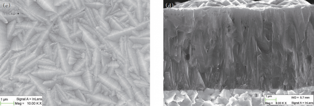
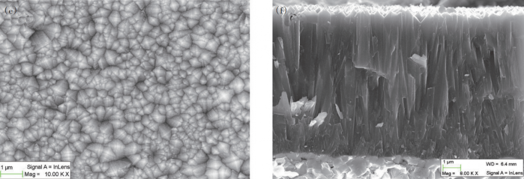
The surface morphology and fracture cross-sections of the three groups of sample coatings were examined by SEM, and the morphology and structure changes of the deposited coatings under different incorporation ratios of CO atmosphere were compared, as shown in Figures 1(a)~1(f). The deposited coatings all have a typical columnar fine-grained structure, and the grain length is close to the coating thickness. The incorporation of CO atmosphere has an obvious effect of refining the grains of the deposited coating, forming a fine-grained fibrous structure, and the content of oxygen added increases with the increase of the CO atmosphere incorporation ratio. Features of fine-grained fibrous structure The more obvious. The average particle size of the 1# test coating is 0.66 μm, the average particle size of the 2# and 3# test coatings is 0.45 μm and 0.3 μm, respectively, and the grain refinement is obvious.
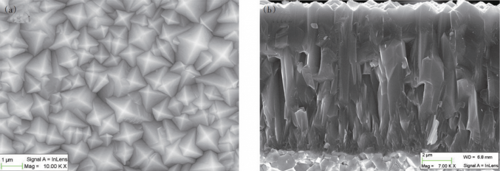
It can also be seen from Fig. 1 that when the CO atmosphere is incorporated, the surface of the grains of the deposited coating forms uneven step marks, resulting in an increase in the surface roughness of the coating and a significant decrease in the surface finish.
2.3 Coating Deposition Rate
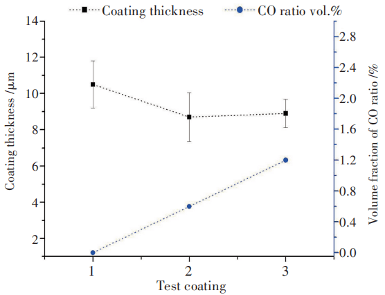
The thickness of the deposited coating is shown in Figure 2 under different atmospheric conditions of CO incorporation ratio. 1# test coating, no CO in the deposition atmosphere, the average coating thickness is 10.5 μm, the deposition rate is about 2.3 μm/h; 2# test coating, 0.6% CO (volume fraction) is mixed into the deposition atmosphere, coating The average thickness is 8.7 μm; 3# test coating, the CO in the deposition atmosphere reaches 1.2% (volume fraction), the average coating thickness is 8.9 μm; the thickness difference between 2# and 3# experimental coatings is normal The thickness fluctuates and the deposition rate is the same, averaging about 1.9 μm/h.
In the deposition system of MT-TiCN coating, CO atmosphere is added for oxygen doping. In the case where the proportion of other reaction atmospheres remains unchanged, the CO atmosphere incorporation ratio (volume fraction) increases from 0.6% to 1.2% by 50%. The thickness of the deposited coating remains unchanged and the deposition rate is not affected. Therefore, the thickness of the 2# and 3# test coatings was reduced by about 19% compared to the 1# test coating, mainly due to the change in the proportion of the CH₃CN atmosphere in the C source precursor reactant in the deposition system.
2.4 Coating Orientation Texture
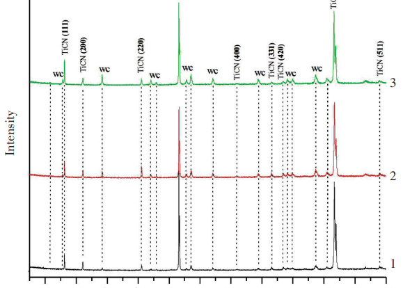
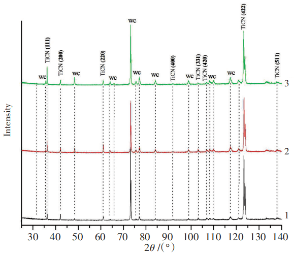
The growth orientation texture of the MT-TiCN coating grains was analyzed by XRD detection. The XRD diffraction peak of the MT-TiCN coating was calibrated using the standard spectrum JCPD/PDF card number 42-1489 diffraction peak, and the XRD spectrum of the test coating was obtained. Figure, as shown in Figure 3
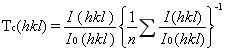
According to the XRD diffraction peak intensity of the test coating in Figure 3, the crystal plane texture coefficient Tc is used to quantitatively describe the growth orientation texture of the MT-TiCN coating. The size of the Tc value reflects the preferential growth direction of the coating, where, I (hkl) is the crystal plane intensity of the coating (hkl) measured by XRD; I0 (hkl) is the standard diffraction peak intensity of the crystal plane of the coating (hkl); n is the number of crystal planes calculated statistically.
The calculation results are shown in Table 4.
The deposited MT-TiCN coatings all have strong T (c 422) orientation texture values, and the preferential growth directions of the coatings are the same. However, with the increase of the proportion of CO atmosphere added in the deposition system, the coating growth orientation texture value Tc (422) showed a downward trend, Tc (111) increased from 0.4 to 0.7, and the growth orientation trend of the most densely packed crystal planes was increasing , That is, a certain amount of CO atmosphere is incorporated into the MT-TiCN deposition system, which promotes the trend of the grain growth of the deposited coating to the most densely packed crystal plane (111), forming a more dense and wear-resistant oxygen-doped MT-TiCN coating.
| Test coating | Tc(111) | Tc(200) | Tc(220) | Tc(400) | Tc(331) | Tc(420) | Tc(422) | Tc(511) |
|---|---|---|---|---|---|---|---|---|
| 1 | 0.4 | 0.1 | 0.2 | 0.4 | 0.3 | 0.3 | 6.0 | 0.2 |
| 2 | 0.4 | 0.1 | 0.4 | 0.5 | 0.4 | 0.4 | 5.4 | 0.3 |
| 3 | 0.7 | 0.1 | 0.3 | 0.6 | 0.5 | 0.3 | 5.2 | 0.3 |
2.5 Nano Hardness of Coating
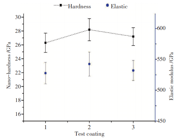
The nanohardness test results of the test coating are shown in Figure 4. The nano hardness of the 1# experimental coating is 26.3±1.4 GPa, the nano hardness of the 2# experimental coating and the 3# experimental coating are 28.2±1.6 GPa, 27.2±1.3 GPa, respectively, which are different degrees from the 1# experimental coating The improvement of the elastic modulus of the test coating is consistent with the change trend of the nano hardness.
of test coatings
In the deposition system, CO atmosphere is doped to form an oxygen-doped MT-TiCN coating, and its nano-hardness and elastic modulus tend to increase, but it does not increase with the increase of the oxygen doping ratio. Combined with the changes in the morphology and structure of the test coating and the grain growth texture orientation results, the 3# experimental coating has a more obvious ultra-fine crystal structure and the most densely packed crystal plane (111) growth orientation enhancement trend, but its nano hardness value Compared with the 2# test coating, there is no increase.
The change of coating nano-hardness is due to the oxygen doping of MT-TiCN and the grain refinement, and it may also be related to the change of the residual tensile stress of the coating. L.von Fieandt and others have shown that the effect of the MT-TiCN coating stress state on nano-hardness is extremely obvious. Under low tensile stress, the MT-TiCN coating with a fine columnar structure has a nano-hardness The typical range is about 22~24 GPa; after the coating process is changed, the coating is under compressive stress and the compressive stress is about -1.6 GPa. Even if the MT-TiCN coating has a multiplied particle size and has a thick flat structure, its Nano hardness has also been significantly improved, reaching 37-38 GPa level. In addition, C. Czettl [13] and other studies have shown that, under the parameters of its deposition system, the residual tensile stress of TiCN coating obtained by doping with 1.5% CO (volume fraction) deposition is the smallest, and the nano-hardness and elastic modulus of the coating are improved. to reach maximum.
2.6 Coating Cutting Performance
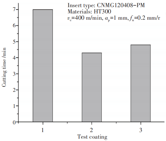
Single-layer test coated blade turning HT300 material wear resistance test results, as shown in Figure 5, according to the cutting edge wear failure standard, the life of 1# coated blade is 7 min, 2# and 3# coated blade, Cutting life is less than 5 min.
Gray iron HT300 is relatively low in hardness and strength and is prone to chipping chips. Such chips are very small. During the cutting process, they enter the surface gap of the cutting edge area of the blade, causing the relative movement of the blade coating surface to be destroyed. For coatings with large surface roughness, abrasive wear during this cutting process is more severe. The difference in the wear resistance of the test coated blade turning HT300 is on the one hand due to the thickness of the coating of the 1# sample compared with the 2# and 3# samples, which is about 1.7 μm thick; on the other hand, the deposition of 2# and 3# The surface finish of the coating is obviously poor, the surface is rough, there are step cracks on the surface of the particles, and the performance of anti-abrasive wear is poor.
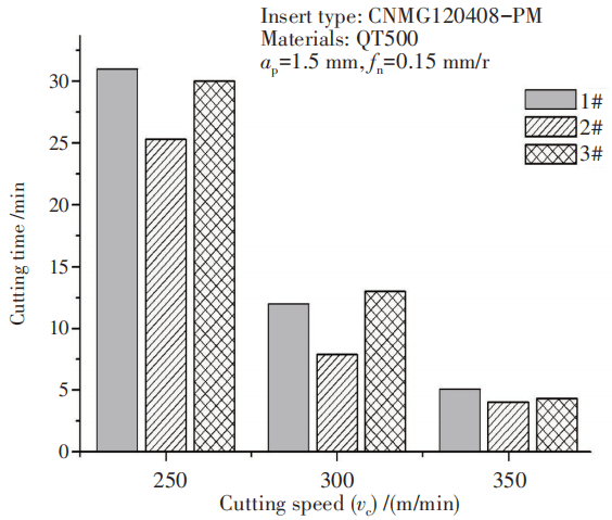
The comparison of the results of turning QT500 material at different cutting speeds with single-layer test coated inserts is shown in Figure 6. The cutting time of 3# coated blades is 30, 13 min and 4 min 20 s in sequence, and the wear resistance at low and medium speeds is equivalent to the 1# coated blade with slightly larger coating thickness, and the 2# with the same thickness Compared with coated blades, the wear resistance is significantly better.
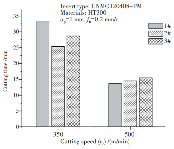
On the surface of the three sets of single-layer test coated blades, a layer of a-Al₂O₃ with a thickness of 4 μm was deposited by the same CVD process to form a TiN/MT-TiCN/Al₂O₃ composite multilayer-coated blade. The results of medium and high speed turning are shown in Figure 7.
The cutting speed vc=350 m/min, the time of 1#~3# composite coated blades are 33, 25 min and 29 min respectively. The change of wear resistance is consistent with the change trend of the cutting performance of single-layer test coated blades.
At a cutting speed of vc=500 m/min, the cutting performance of 2# and 3# composite coating blades are slightly better than 1# composite coating blades. In the HT300 high-speed turning, the main form of cutting wear is blade flank face wear. 2# and 3# oxygen-doped MT-TiCN coated inserts have the fine-grained high hardness performance and play a better wear resistance. The characteristics are enough to offset the difference in cutting performance caused by the coating thickness difference of 1# blade.
In Conclusion
In the existing CVD preparation atmosphere system of MT-TiCN coating, doping with different proportions of CO, and performing oxygen-doped MT-TiCN deposition preparation, and analyzing the influence of oxygen doping on the coating structure and performance, the conclusions are as follows:
- The grains of the oxygen-doped MT-TiCN coating are obviously refined, forming a fine-grained fibrous structure, but the surface roughness is increased.
- Oxygen doping has no effect on the deposition rate of the coating, only the oxygen content in the coating composition increases, the reaction mechanism is that oxygen replaces hydrogen in the coating; the nano-hardness and elastic modulus of the coating increase.
- The deposited coatings all have strong Tc (422) texture values, and the preferential growth direction of the coatings is the same; while oxygen doping promotes the growth of the coating grains toward the most densely packed crystal plane (111).
- Single-layer oxygen-doped MT-TiCN coating inserts have reduced abrasive wear resistance, while in high-speed cutting with adhesive wear, oxygen-doped MT-TiCN coating with ultra-fine grain and high hardness The cutting insert and its multi-layer coated cutting insert compounded with Al₂O₃ coating have shown good wear resistance.